Every photograph and video here is Jayess equipment at the Jayess works. Nothing is stock,
nothing is generated, and nothing is another manufacturer's product. Captions state what the
frame cannot — the stage, and any rating legible on the unit itself.
Assembly
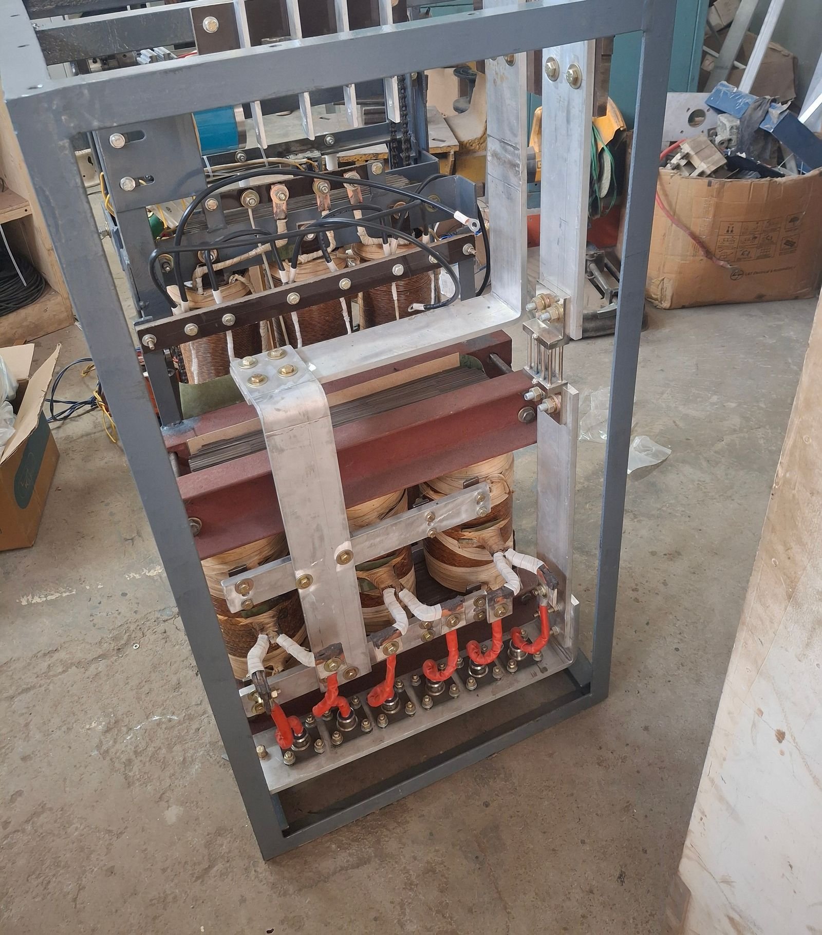
Servo voltage stabiliser under assembly at the works — buck-boost winding above, variable winding assembly below
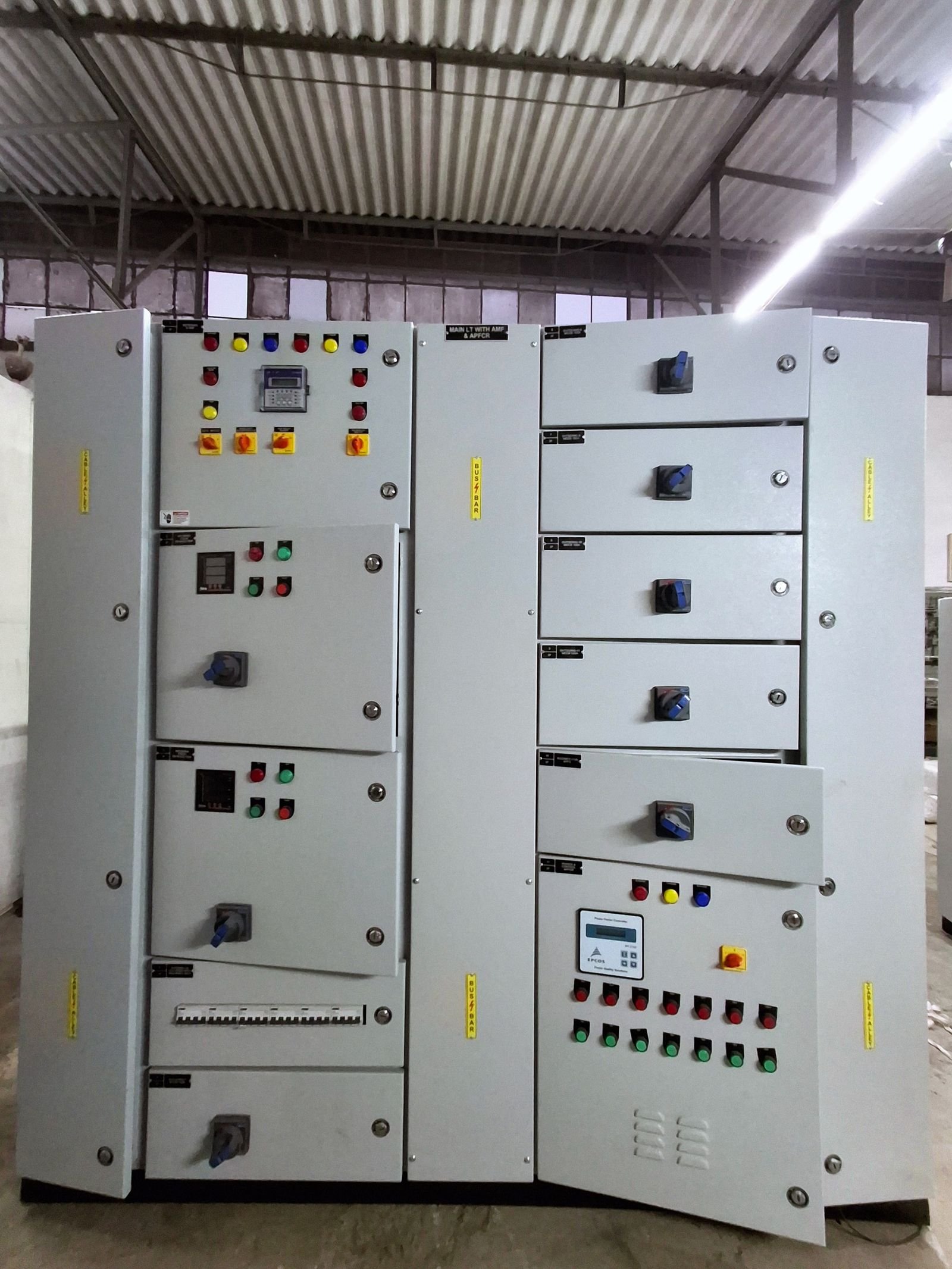
Main LT panel combining AMF and APFC(R) in one board. Busbar chamber and cable alleys are labelled as separate vertical compartments; the power factor controller sits at the door of the correction sectionMAIN LT WITH AMF & APFCR — read from the designation label, not a rangeCore-and-coil assembly lifted in the yard. Windings on all three limbs are visible before tanking.8s · Faridabad works
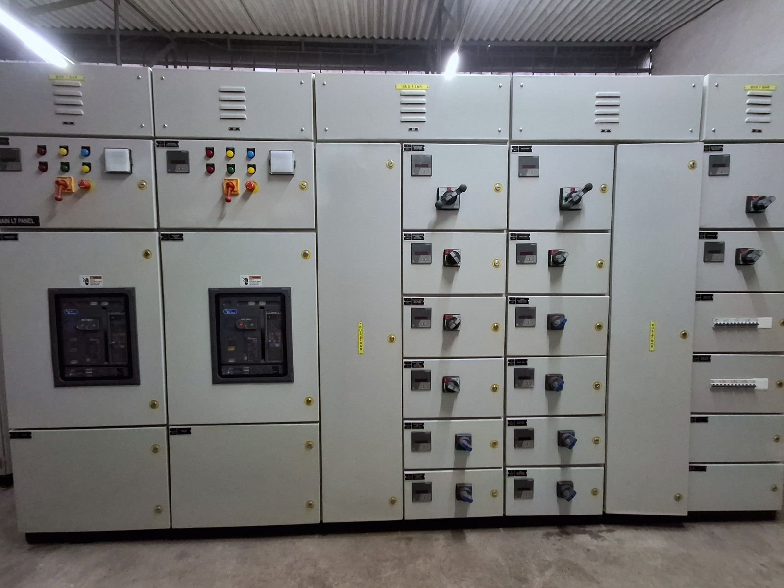
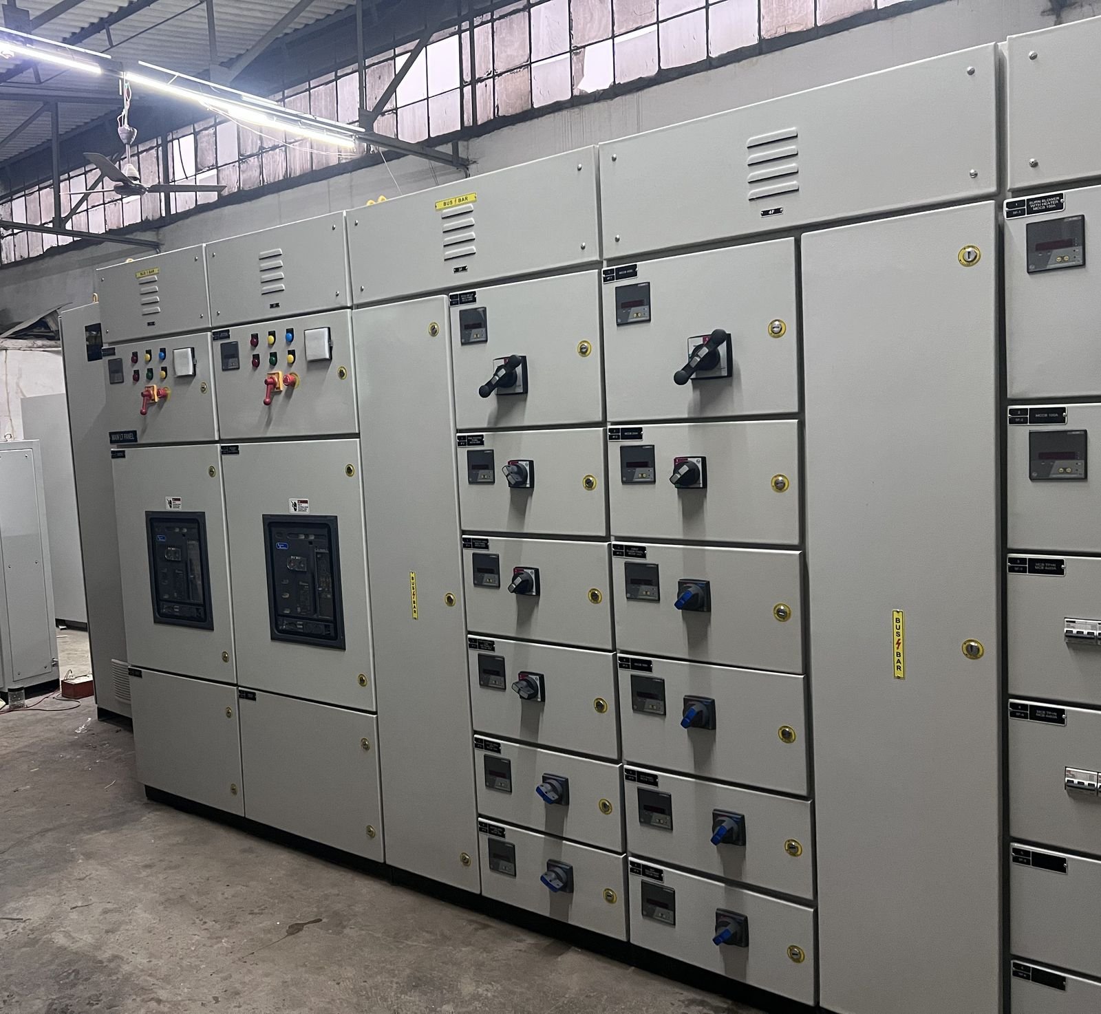
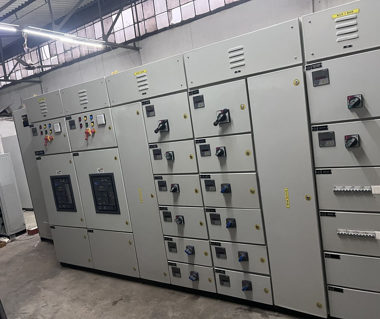
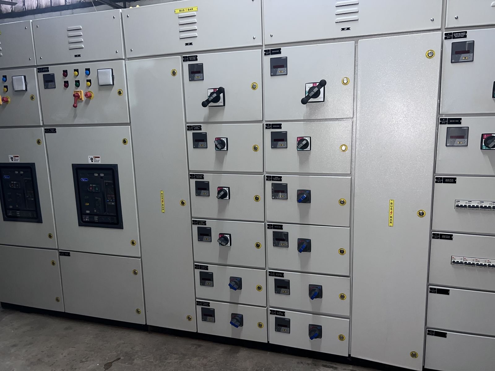
Main LT panel lineup at the works, doors closed. The two glazed windows on the left are the incomer breakers; every compartment to the right is an outgoing feeder with its own meter and switch-disconnectorMAIN LT PANEL — read from the designation label, not a range
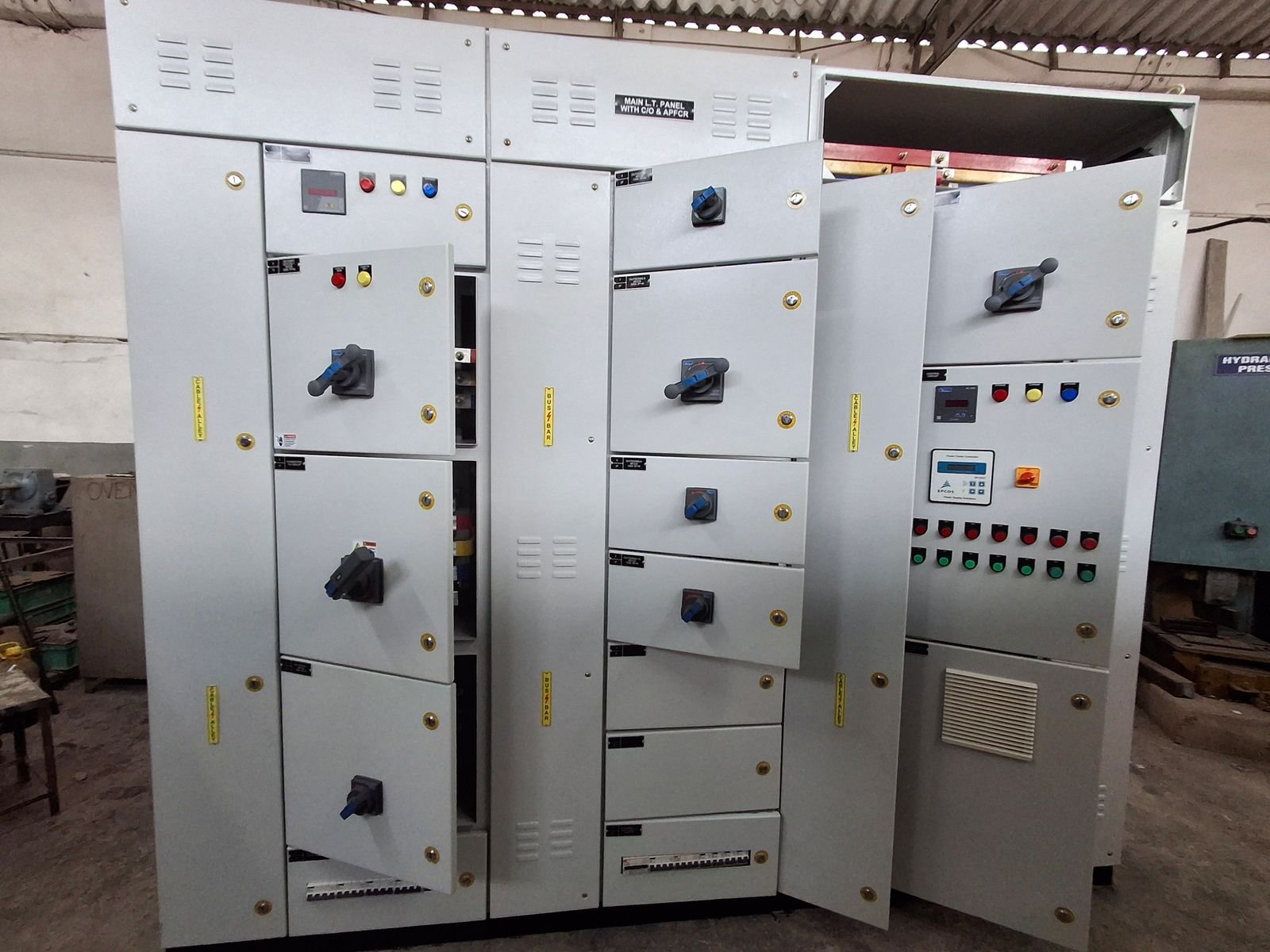
Main LT panel with DG changeover and automatic power factor correction, doors open on the works floor before final wiring checksMAIN L.T. PANEL WITH DG & APFCR — read from the designation label, not a range
LT lineup on the works floor, seen along its length from the incomer end
The full run of the lineup, busbar chambers labelled along the top. Compartments are built out as separate verticals and bolted togetherBUS BAR — read from the designation label, not a range
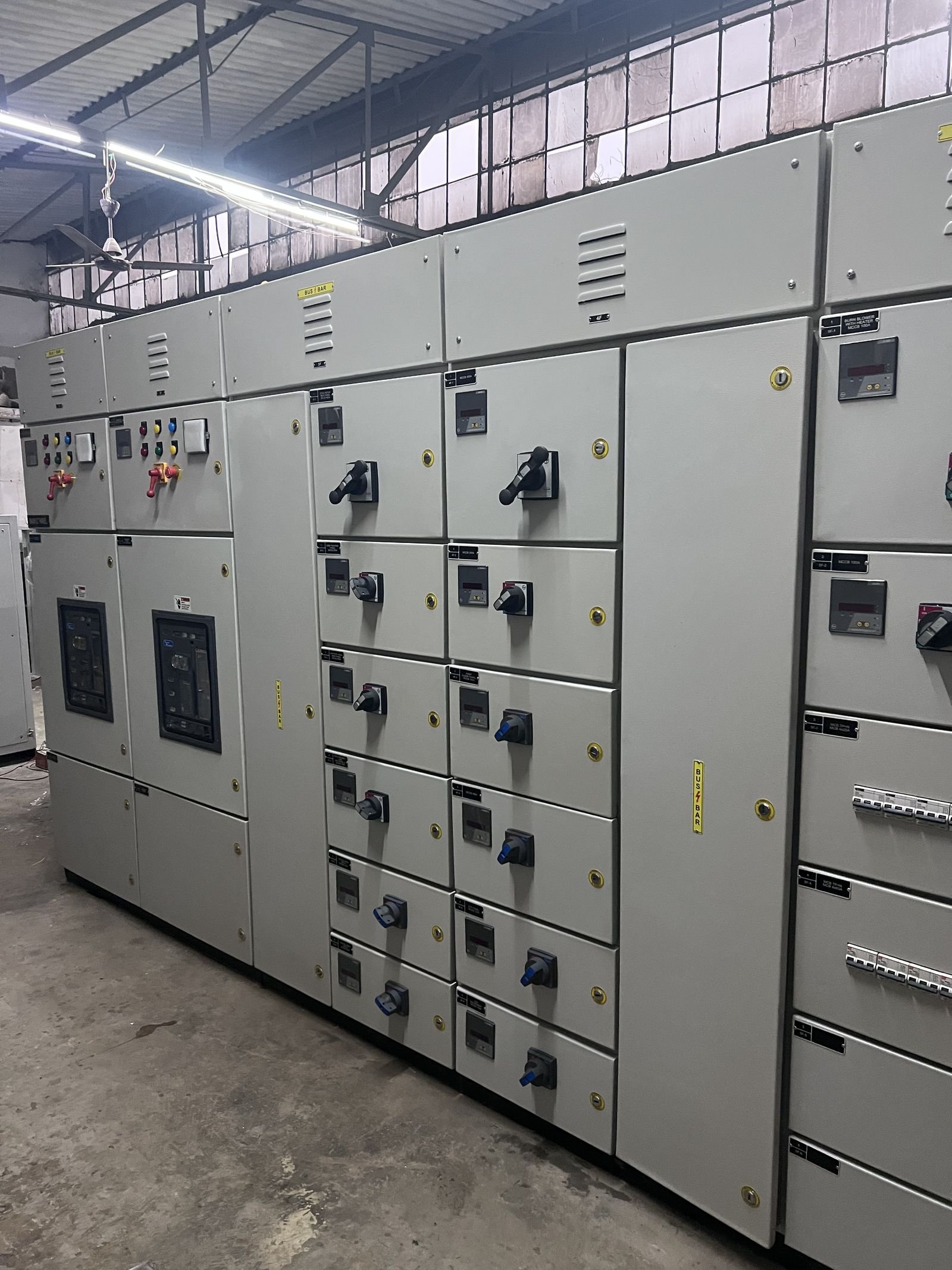
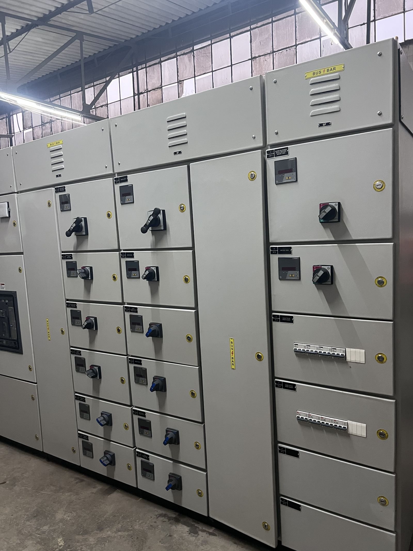
Outgoing feeder compartments, each with its own meter, switch-disconnector and engraved label. The feeder schedule is what sets the compartment count
Busbar chambers labelled and louvred along the top, feeder compartments below, with a distribution section of miniature breakers at the rightBUS BAR — read from the designation label, not a range
Incomer breakers behind glazed windows on the left, outgoing feeders across the centre, miniature breaker distribution at the right
Testing
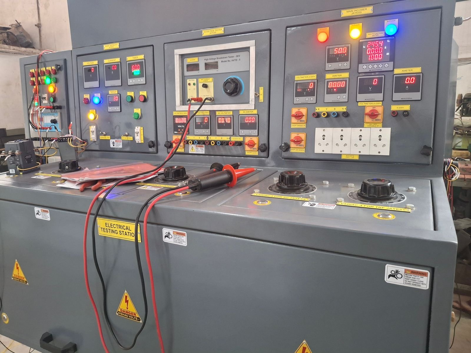
Electrical testing station at the works. The console carries a 5 kV high-voltage breakdown tester and four variacs labelled for transformer testingHigh Voltage Breakdown Tester 5 kV, model HVTD-5 — read from the nameplate, not a range
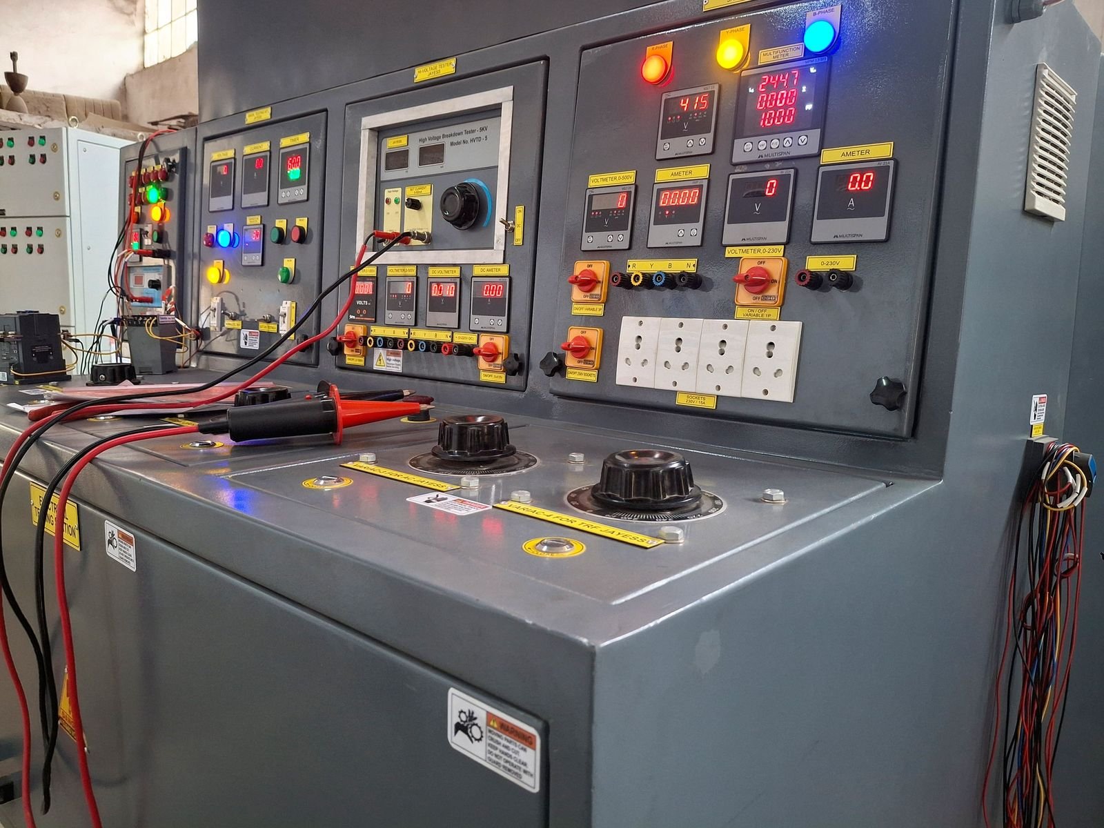
Testing station, oblique view — instruments energised during a testLineup energised at the works with indication live. Works testing precedes dispatch on every assembly.21s · Faridabad works
Dispatch
Wrapped for transport and lifted out by crane. The orange control section on top carries the indication and metering fascia.20s · Faridabad worksFinished front elevation before dispatch. Metering at the top, rotary selectors on each compartment door.14s · Faridabad worksServo voltage stabiliser on its transport base, controller fascia fitted. No nameplate is legible, so no rating is stated.16s · Faridabad worksRadiator banks either side of the tank, controller mounted on top. No nameplate is legible in the frame, so no rating or voltage class is stated.24s · Faridabad works
Installed
Standing on its plinth under cover. Metering and indication run across the upper fascia.28s · Faridabad works
Photographs and video currently on file are working copies rather than camera originals, so
they are published at the size they were supplied. Video plays only when you press play —
nothing downloads before that. Originals are being recovered, after which these frames will
be re-derived at full resolution.
Visit the works
Photographs are a poor substitute for standing in front of the plant. If you are specifying equipment, ask for a works visit.